icons-Service

Drastically reduce your time and cost of installation and integration.

GroupCreated with Sketch.

Spiral conveyor installation and integration directly affect startup speed, long-term reliability, and conveyor line performance. Most Ryson Spirals are shipped pre-assembled and pre-tested, which helps reduce field installation time and lower implementation risk. This page explains how to install a Ryson Spiral Conveyor, what startup checks to complete, and what controls, transitions, speeds, and safety settings are required for successful integration.

Download the installation guide, request service support, or contact Ryson for help planning your system.

#1 Manufacturer of Spiral Conveyors in USA

Ryson Spiral Installation Guide

Before putting a Ryson Spiral Conveyor into full operation, confirm that all startup and integration requirements have been completed. Ryson spirals are shop tested before shipment, but reliable field performance still depends on proper installation, controls integration, and startup verification.

Spiral Installation and Integration Start-up Check List

  1. Check to make sure that all integration instructions are implemented.
  2. Check the chain-tensioner for the proper chain tension adjustments. Remove the red chain shortening tool (shipping nut) if installed. Save tool for future use.
  3. Check that all side guides are in place and adjusted correctly.
  4. Set the adjustable transition rollers and/or transition plates. Check height adjustments to assure smooth product flow over transitions.
  5. Check gear motor for oil level and breather plug. Remove vent shipping grommet IF installed.
  6. BUMP motor and check spiral direction. Run spiral at slow speed at initial startup and check for any parts that may have come loose during shipment
  7. Check proximity sensors for power and function.
  8. Check VFD ramp-up. The acceleration parameter should be 3 to 5 seconds depending on spiral height.
  9. Check VFD ramp-down. The deceleration parameter should be a minimum of 3 seconds.
  10. Run test product and set overload device as necessary with a fully loaded spiral.

Most Ryson Spirals are shipped in one piece pre-assembled and pre-tested, drastically reducing the time and cost of installation.

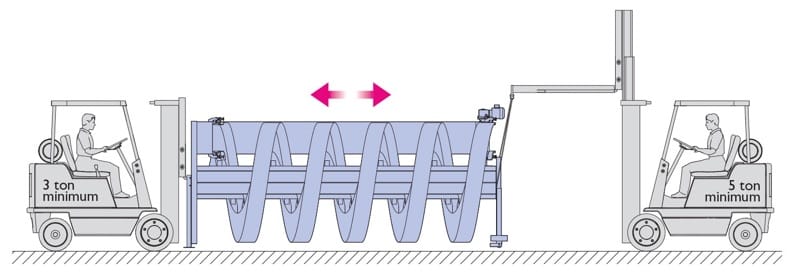
Most Ryson Spirals are shipped in one piece, pre-assembled and pre-tested, which can significantly reduce installation time and field labor. Some units ship with detached components for transportation purposes, especially models with extended infeed or outfeed tangents or diameters greater than 8 feet.

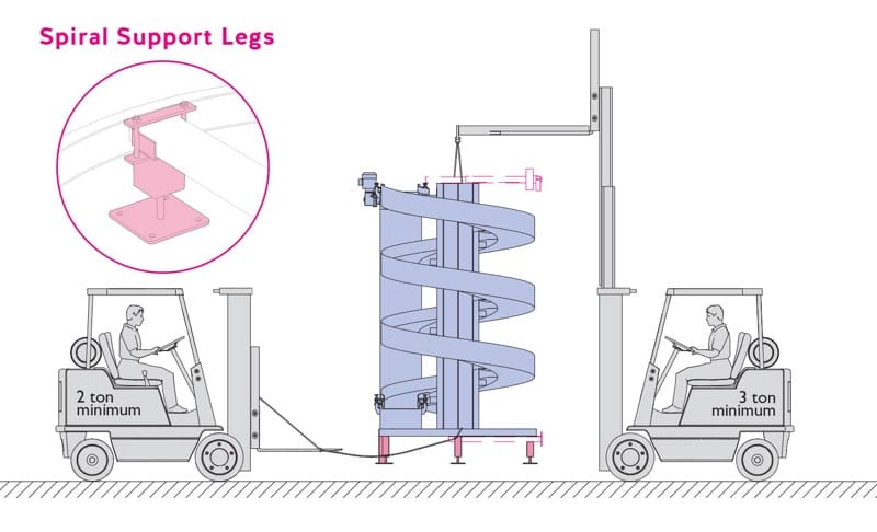
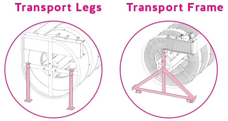
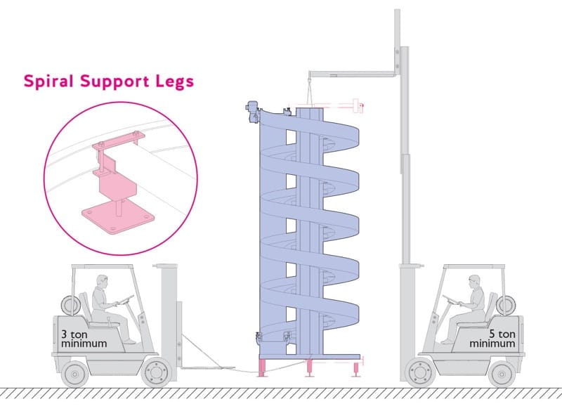
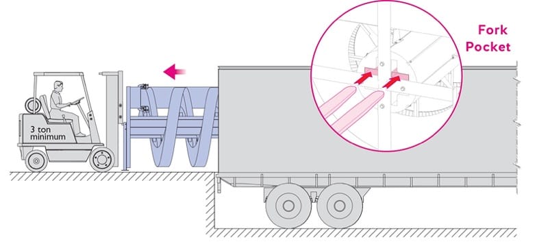
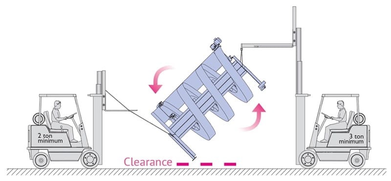
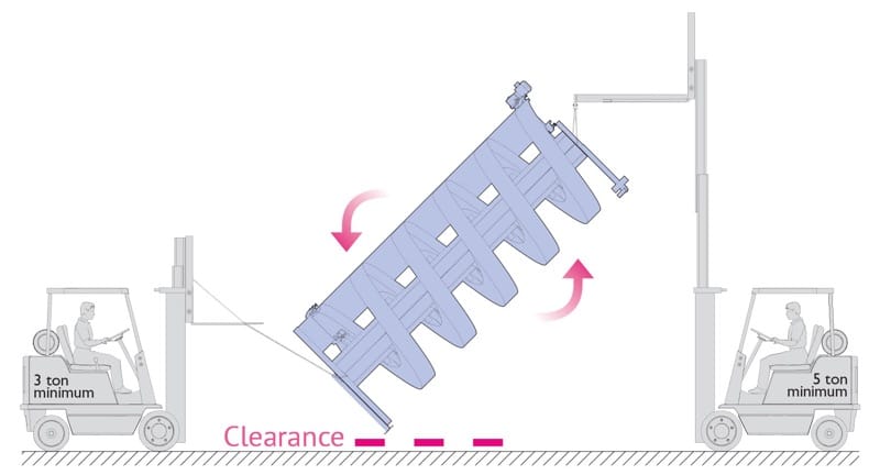
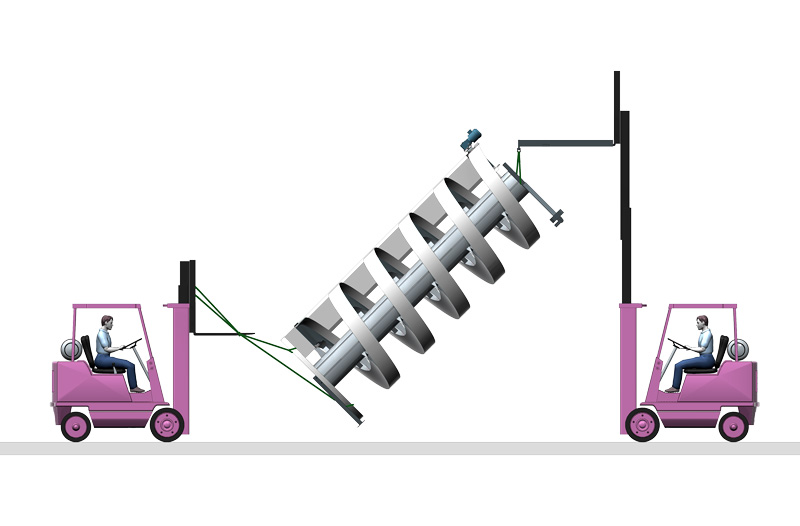
All spirals are shipped in an A-frame with casters to simplify unloading and movement to the installation area. Reinforced fork pockets in the center tube are provided for safe horizontal forklift handling, and the top end of the center tube is used for rigging when standing the spiral upright.

Spirals shorter then 16 feet
For shorter spirals, safe installation begins with correct unloading, careful transport, controlled rigging, and proper support-leg installation.
Unloading Spiral

Only use the two reinforced fork pockets provided in the bottom end of the center tube when unloading and transporting the spiral

How to unload a Ryson Spiral
Transporting Spiral

Lift the pocket end of the spiral and move carefully while the transport frame (with casters) is supporting the opposite end.

Standing Up Spiral

The top end of the center tube is used for rigging when standing up the spiral. Use only properly rated wire rope or chain slings. Use a forklift or boom truck. Use a second forklift to assist and to make sure the spiral clears the floor when lifting. Use only properly rated poly slings or straps.

Caution: Check to make sure all slings and straps are properly secured before lifting.

How to stand up a Ryson Spiral
Installing Legs

Remove transport legs and install the spiral support legs (bolts down) while the spiral is hanging. Remove transport frame when spiral is standing.

Spirals taller then 16 feet
Taller spirals follow the same general process but require more lifting control and, in many cases, additional handling equipment.
Unloading Spiral

Only use the two reinforced fork pockets provided in the bottom end of the center tube when unloading and transporting the spiral

How to unload a Ryson Spiral
Transporting Spiral

Lift the pocket end of the spiral and move carefully. A second forklift is required to maneuver and turn the spiral in tight area.

Standing Up Spiral

The top end of the center tube is used for rigging when standing up the spiral. Use only properly rated wire rope or chain slings. Use a boom truck or crane. A crane is necessary for spirals above 24 feet. Use a second forklift to assist and to make sure the spiral clears the floor when lifting. Use only properly rated poly slings or straps.

Caution: Check to make sure all slings and straps are properly secured before lifting.

How to stand up a Ryson Spiral
Installing Legs

Remove transport legs and install the spiral support legs (bolts down) while the spiral is hanging. Remove transport frame when spiral is standing.

Proper spiral conveyor integration is critical for optimal performance, equipment life, and warranty protection. Ryson Spirals are tested before shipment, but they must be integrated correctly with upstream and downstream conveyors, controls, and safety logic to operate reliably in the field.

All Ryson Spiral Conveyors are shop tested prior to shipment, but depend on proper spiral integration with the overall conveyor system for optimal performance. Failure to follow these guidelines will adversely affect spiral performance, longevity and may also void the warranty.

For more detailed information on proper spiral integration, consult the matching section in the manual provided with your spiral.

Conveyor Controls
(section 4.1.1)
  • The controls must be designed to prevent unintended accumulation and prevent product back-ups in the spiral.
  • The controls should be set up in a cascading control method.
  • The in feed conveyor should not start until the spiral is running at full speed.
  • The spiral must stop anytime the out feed conveyor is full or stopped.
Conveyor Speeds
(section 4.1.2)
  • The speeds of the in-feed, spiral and out-feed conveyors must be matched. Max. speed 200 fpm.
  • A speed differential between these conveyors will lead to premature wear of the friction inserts and the chain assembly.
A VFD is required
(section 4.1.3)
  • A VFD (variable frequency drive) is required for the proper operation of the spiral.
  • The spiral controls must utilize an acceleration of a minimum 3-5 sec. Longer ramp-up may be needed for taller spirals and heavy loads.
  • The spiral controls must utilize a deceleration of a minimum 3 sec.
Gap between Loads
(section 4.1.4)
  • There must be a gap between the loads when they enter the spiral.
  • The minimum gap should be ¼ of the product length, but a larger gap may be required for spirals with heavy loads to prevent spiral overloading.
  • The spiral cannot be used to pull a gap between loads.
Conveyor Transitions
(section 4.1.5)
  • The loads must be powered in and out of the spiral.
  • The use of gravity conveyors is not recommended as they do not assure a proper gap between loads.
  • Loads must be positioned within the slat width prior to entering to the spiral
  • Product should be properly turned prior to entering to the spiral
  • The in-feed conveyor should be 1/8” to 1/4 higher than the spiral.
  • The out-feed conveyor should be 1/8” to 1/4 lower than the spiral.
  • The transition rollers on the Ryson Spiral are independently adjustable at the in-feed and out-feed.
Proximity Sensors
(section 4.2.5)
  • Two proximity sensors are utilized on the Ryson Spiral to monitor faults associated with a slack chain or a motor over-torque condition.
  • These proximity sensors must be wired as inputs to the control PLC and programmed as fail-safe devices.
  • Loss of a signal is a fault and the PLC program should immediately (no time delays) shut down the spiral.
  • These faults also need to be programmed as latching manual reset faults which require an operator to reset the controls before the spiral can be re-started.
  • Sensors must be hooked up according to the supplied vendor schematics as they can be damaged if hooked up improperly
  • he following are the Turck sensor schematics (below) which is the Ryson standard.
Motor Brakes
(section 4.4)
  • Most spiral applications do not require a brake. For taller spirals with heavy loads, a brake is used to prevent rollbacks and drifting when the spiral is stopped.
  • The brake must be powered with a dedicated power source separate from the motor.
  • The motor is powered by the VFD and the motor voltage is ramped-up at start-up, but is not sufficient to fully release the brake.
  • The brake must be released (powered) before the motor is started and set (de-energized) after the motor has come to a complete stop.
  • Brake coils from SEW Eurodrive are available in different voltages. Please consult the manual supplied with your spiral for the proper brake voltage.
Chain Tensioner adjustments
(section 6.2)
  • An automatic chain tensioning device has been provided to assure that the chain stays in tension at all times.
  • Operation of the spiral with insufficient chain tension will cause the spiral to malfunction and have premature wear.
  • he tensioner bar position must operate at an angle between 0º (horizontal) and 10º.
  • The compressed spring should measure between 5 and 6-1/2 inches.
  • The tensioner flag should operate between the green and red markers.
  • The slack chain proximity sensor should be adjusted so that the spiral shuts down if the tensioning bar falls below 0º (approximately 2” from the top of the flag to the bottom of the proximity sensor face).
Air Cylinder chain tensioners
(section 4.5)
  • Air cylinders are used instead of the standard spring tensioning device on very tall spirals and with heavy loads or spirals supplied with the reversible option.
  • All air cylinders will have a low air pressure switch, which is used to monitor the supply air and should be hooked up as a N.O. (normally open) device and programmed as fail-safe to shut down the spiral with a latching, manual reset fault.
  • Non-reversible spirals will have one regulator which should be set to 10-15 PSI for proper tension.
  • Reversible Spirals will have a 4-way solenoid valve (24V DC or 110v ac), a shuttle valve and two regulators. The forward (up) direction regulator is to be plumbed to the N.C. (normally closed) porting of the 4-way solenoid valve and the forward regulator set to 10-15 psi. The reverse (down) regulator is to be plumbed to the N.O. (normally open) port of the 4-way solenoid valve and the reverse regulator set to 15-20 psi.
  • The reverse direction of the spiral should be at slow speed, not to exceed 60 fpm.
Motor Overload Adjustments
(section 6.5)
  • An overload protection device with a proximity sensor has been provided to stop the spiral in case of overloading or jamming of the spiral chain
  • The drive motor is mounted on a torque arm bracket with a spring assembly. The spring applies a torque resistance which can be adjusted to the desired torque limit.
  • The torque assembly will pivot when torque exceeds a pre-set limit set by the amount of spring compression.
  • The torque resistance should be set for maximum protection without impeding regular operation.
  • The proximity sensor can also be adjusted vertically and horizontally for more or less torque sensitivity.

Resource

Design Tools

Ryson can provide 3D AutoCAD drawings in addition to the CAD blocks normally provided with our proposals upon request. .

These 3D drawings accurately depict the quoted spirals and can easily be inserted into an overall 3D system drawing or presentation. The 3D drawings can be manipulated within AutoCAD, including color selection and the degree of details needed.

Why Choose Ryson?

Ryson helps reduce installation time and integration risk by shipping many spirals pre-assembled and pre-tested, then supporting the system with practical guidance for startup, controls, transitions, sensors, and long-term maintenance. For engineers, integrators, and operations teams, that means a clearer path to reliable vertical conveying and fewer surprises during commissioning.

Frequently Asked Questions

How do you install a Ryson Spiral Conveyor?

  • Most Ryson Spirals are shipped pre-assembled and pre-tested, which reduces field assembly time. Installation typically includes safe unloading, transport, standing the spiral upright, installing support legs, verifying chain tension and components, and completing startup checks before full-speed operation.

What is required to integrate a spiral conveyor into an existing line?

  • Proper integration requires matched infeed, spiral, and outfeed speeds, correct transition heights, product gaps between loads, fail-safe sensor wiring, and controls that prevent backup or unintended accumulation.

Why is a VFD required on a Ryson Spiral Conveyor?

  • A VFD is required to control ramp-up and ramp-down. Ryson guidance calls for approximately 3-5 seconds of acceleration depending on spiral height and at least 3 seconds of deceleration to protect operation and product flow.

What startup checks should be completed before operation?

  • Key checks include chain tension, side guide placement, transition roller or plate adjustment, motor oil level and breather, motor direction, sensor function, VFD ramp settings, and overload settings under load.

How should upstream and downstream conveyors be configured?

  • The infeed and outfeed conveyors should be powered and speed-matched to the spiral. Ryson also recommends the infeed conveyor be slightly higher and the outfeed slightly lower than the spiral to support smooth transitions.

How much gap is needed between products entering the spiral?

  • Ryson recommends a minimum gap of one-quarter of the product length, though heavier loads may require more space. The spiral should not be used to pull a gap between loads.

When is a motor brake required on a spiral conveyor?

  • Most applications do not require a brake. However, taller spirals with heavy loads may need a brake to prevent rollback or drift when the spiral stops.

Can gravity conveyors be used with a spiral conveyor?

  • Ryson does not recommend gravity conveyors for spiral transitions because they do not ensure proper product gap or controlled flow into the spiral.

The Ryson Parts and Service Department is always available to assist

Every day we strive to develop and deliver products and services that help our customers grow. Because standing still brings you nowhere, it might even move you backwards. Especially when it comes to the production lines of our customers.
Our people show the joy, passion and expertise to develop the best machines & deliver the best service globally! Everyone knows our company’s goals we have set, and in his or her own way is actively contributing towards reaching our goals.